The OPM500 measures optical power via a photodiode. Photodiodes are useful for power measurement in the visible and near infra-red due to their inherent sensitivity and speed of measurement.
Photodiodes produce a current which is proportional to the incident light power over a wide dynamic range. The disadvantage when compared to calorimetric devices is the wavelength dependance. However, for use with monochromatic sources, the detector can be calibrated and the measured current corrected accordingly.
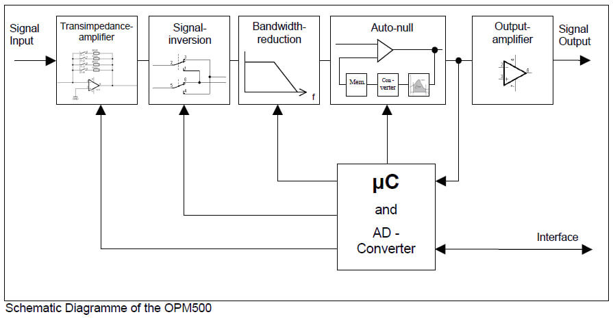
The current from the photodiode is converted to a voltage through a precise transimpedance amplifier. This amplifier is very linear over the full measurement range of the device. The OPM500 has 6 gain ranges. The switch is a semiconductor device, free from degradation. A unique feature of the OPM500 is the auto-null function. Further functions include signal inversion and bandwidth reduction. The analogue output signal is available at the BNC connector on the front panel an on the appropriate line on the interface port on the back panel.
The voltage generated is then converted to a digital value via a 12 bit A/D converter. This process and all calculations and communication with the PC are controlled by a microcontroller. The measurement process is started via a command over the USB interface (software trigger). Alternatively, a continuous measurement stream can be started which samples at 600 S/s.
The measured photocurrent may also be read out from the USB port. In addition, the calibration value for a given wavelength may be read out. Using these two values, the optical power can then be calculated.
This optical power monitor is particularly useful for the measurement of fibre coupled sources. The output is a voltage linearly proportional to input power. The fast response time at high signal-noise ratio makes this OPM series particularly useful in systems control feedback loops.
The high sensitivity and large dynamic range allow measurement of a wide range of optical sources such as lasers and LEDs alike.
The OPM500 series is insensitive to electromagnetic interference by design, an important factor when working in “dirty” industrial environments. The proprietary auto-nulling function allows up to 10V of offset nulling. This is particularly useful for nulling dark current or for eliminating a DC signal component to concentrate on signal changes, such as in component burn-in and life-time testing.
| Parameter | Conditions | Si, InGaAs | Ge | Units | ||||
|---|---|---|---|---|---|---|---|---|
| Input | ||||||||
| Wavelength range | extended InGaAs | 1000 – 2200 | 800 – 1550 | nm | ||||
| InGaAs | 800 – 2000 | nm | ||||||
| visible enhanced InGaAs | 400 – 1600 | nm | ||||||
| UV-Si | 250 – 1100 | nm | ||||||
| Power ranges (full scale) | + 51 0 – 10 – 20 – 30 – 40 | + 15 + 10 0 – 10 – 20 – 30 | dBm | |||||
| Noise equivalent power (NEPRMS ) | Range 1 – 5 Range 6 | full scale – 45 (max) – 75 (max) | full scale – 32 (max) – 62 (max) | dB dBm | ||||
| Polarization Dependant Loss (PDL) | 0.02 – 0.1 | 0.02 – 0.1 | dB | |||||
| Fibre type | single mode, multi-mode (core Φ ≤ 62.5 μm; NA ≤ 0.275) | single mode, multi-mode (core Φ ≤ 62.5 μm; NA ≤ 0.275) | ||||||
| Receptacles | FC, SMA, free beam | FC, SMA, free beam | ||||||
| Output | ||||||||
| Function | Linear analogue : Vout = scale factor x Pin | Linear analogue : Vout = scale factor x Pin | ||||||
| Output scale | Range 1 Range 2 Range 3 Range 4 Range 5 Range 6 | 11 10 100 1 10 100 | 0,1 1 10 0,1 1 10 | V/mW V/mW V/mW V/µW V/µW V/µW | ||||
| Output range (full scale) | 10 (max) | 10 (max) | V | |||||
| Connectors | BNC and DB25 (Adapters for other connector systems available) | BNC and DB25 (Adapters for other connector systems available) | ||||||
| Rise / Fall time (10% – 90%) | Small signal (-1 → +1V) Large signal (-10 → +10V) | 45 (max) 65 (max) | 45 (max) 65 (max) | µs | ||||
| Accuracy | ± 5 (min) | ± 5 (min) | % | |||||
| Reproducibility | ± 0.5 (min) | ± 0.5 (min) | % | |||||
| Linearity | ± 0.1 (typ) ± 0.2 (max) | ± 0.1 (typ) ± 0.2 (max) | dB | |||||
| Output impedance | BNC-Output DB25-Output | 50 0 | 50 0 | Ω | ||||
| Logic | ||||||||
| Current required for switching | – 10 (min) 0.01 (typ) 10 (max) | – 10 (min) 0.01 (typ) 10 (max) | µA | |||||
| Switching time | 1502 (max) | 1502 (max) | µs | |||||
| Power supply | ||||||||
| Type | Wall plug (supplied) | Wall plug (supplied) | ||||||
| Dimensions | 30 x 50 x 60 | 30 x 50 x 60 | mm | |||||
| Dimensions | ||||||||
| 1053 x 45 x 116 (B x H x L) | 1053 x 45 x 116 (B x H x L) | mm | ||||||
1 Linearity guaranteed to 0dBm (1 mW).
2 Logic switching < 1µs. Effective switching time limited by setting time.
3 130 mm including case wings.


Instruments