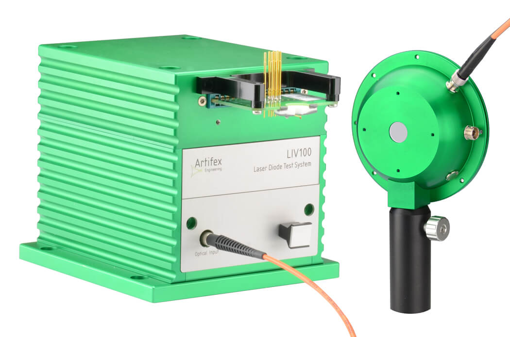
The LIV100 is a short pulse test system for the characterization of laser diodes and LEDs at the chip, bar or submount level.
The fast rise time with essentially no overshoot allows testing these thermally “naked” devices without undue thermal loading.
We offer three versions of the LIV100 differing in speed and pulse length.
Each version is available in any given maximum current (denoted by “xxx” in the list below).
All three systems are controlled via a USB port for automated liv measurements. A parameter set is uploaded from the control computer.
Following the start command, the LIVs then perform the complete measurement sequence fully autonomously.
The fast data acquisition provides for high throughput.
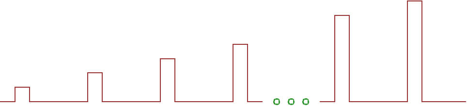
The burst mode is used to run the driver at constant current with a single pulse (or step) width and pulse separation during the whole burst. The laser power is measured for each pulse in this mode. Schematically this appears as follows:

The burst mode is useful for checking the thermal contact on a device or for generating light for a certain length of time for other measurements such as smile, near field / far field patterns or spectra.
Artifex Engineering supports this laser diode characterization system with a custom strip line or contact card configuration service.
Applications include laser diode characterization before and after submounting or packaging, inspection of incoming goods and for OEMs.
The software delivered with the unit allows for one-click generation of a full pdf data sheet for the device under test.
The short pulse capability of the laser diode characterization system LIV100 ensures that the device under test can be measured with negligible thermal loading.
This fact can be exploited to determine the thermal resistance of the contact to a submount or package (see the “Tutorial” and “Downloads” tab).
| Parameter | Conditions | Resolution | Min | Typ | Max | Unit | ||||||
|---|---|---|---|---|---|---|---|---|---|---|---|---|
Inputs:
| ||||||||||||
| Sampling rate | selectable: 20/n MS/s with n=1..20 | n.a. | 1 | 20 | MS/s | |||||||
| A/D Resolution | 13 | bit | ||||||||||
| Photodiode gain | optimum gain automatically selected | 1 10 | V/mA | |||||||||
| Transimpedance amplifier rise time1 | Input capacitance <20pF, gain = 1kΩ | 50 | ns | |||||||||
| Output | ||||||||||||
| Pulse duration2 version F | 20MS/s sampling rate 1MS/s sampling rate | 0.050 1 | 0.150 1 | 100 2000 | µs | |||||||
| Pulse duration2 version L | 20MS/s sampling rate 1MS/s sampling rate | 0.050 1 | 2 2 | 100 2000 | µs | |||||||
| Pulse duration2 version XL | 20MS/s sampling rate 1MS/s sampling rate | 0.050 1 | 5 5 | 100 2000 | µs | |||||||
| Rise time | F L XL | 701 420 700 | 100 500 1000 | ns | ||||||||
| Current overshoot at maximum current5 | 0 | 5 | % | |||||||||
| Pulse separation | selectable: 50 ·n µs with n= 2..10 000 | 50 | 100 | 500 000 | µs | |||||||
| Repetition rate | 100 | kHz | ||||||||||
Current range | LIV100-F002, -L002 or -XL002 LIV100-F040, -L040 or -XL040 LIV100-F080, -L080 or -XL080 LIV100-F120, -L120 or -XL120 LIV100-L200 or -XL200 LIV120-XL400 LIV120-XL600 | 0.0005 0.01 0.02 0.03 0.05 0.10 0.15 | 0.01 0.2 0.4 0.6 1.0 2.0 2.0 | 2 40 80 120 200 400 600 | A | |||||||
| D/A resolution | 12 | bit | ||||||||||
| Compliance voltage | 8 | V | ||||||||||
| Duty cycle quick rise version (examples only: any current range from 1A to 600A may be specified at time of purchase) | LIV100-F002 LIV100-F040 LIV100-F080 LIV100-F120 | 25 1.5 0.7 0.5 | % | |||||||||
| Duty cycle long pulse version (examples only: any current range from 1A to 600A may be specified at time of purchase) | LIV100-L002 LIV100-L040 LIV100-L080 LIV100-L120 LIV100-L200 | 35 2.9 1.5 1.0 0.6 | % | |||||||||
| Duty cycle long pulse version (examples only: any current range from 1A to 600A may be specified at time of purchase) | LIV100-XL002 LIV100-XL040 LIV100-XL080 LIV100-XL120 LIV100-XL200 LIV100-XL400 LIV100-XL600 | 35 2.9 1.5 1.0 0.6 0.3 0.2 | % | |||||||||
| Signal processing | ||||||||||||
| Depth of storage | 512 | kB | ||||||||||
| Number of channels | 1 | 1 | 250 | |||||||||
| PC Interface | ||||||||||||
| Type | USB; 100kB/s | |||||||||||
| Dimensions | ||||||||||||
| DAQ unit | 114 x 150 x 125 (w x l x h) | mm | ||||||||||
1 F-versions at 60A. The maximum available current for the F-version is 120A.
2 With 2µs pulse width. Measurement of 200 pulses and 0,2% duty cycle.
3 Per ANSI/IEEE standard 181-1977: 10% – 90%.
4 Optimum sampling rate is automatically selected.
5 With optimized strip line connector, no load matching required
We will gladly adapt, for example, the wavelength or the current to suit your application. Let us know your requirements.

By loading the video, you agree to YouTube's privacy policy.
Learn more


CUSTOMIZED SOLUTIONS

OPTICS

Instruments